当社では以前、MONOist様の記事、及び研究にてIsaac Simと実機の位置同期の検証を行いましたが、当社ではUnityについても取り扱っています。
この記事ではUnityとGazeboを用いて、Turtlebot3の位置同期を実現する手法について解説します。
今回はより他のユーザでも再現できる環境を提供するため、Gazeboを利用した位置同期を行います。
具体的にはGazebo側のロボットを動かすと、その動きがUnityのロボットに同期して反映されるようになります。
さらに、Unity側のロボットにセンサーを搭載し、センサーの距離によってロボットの動きを制御する方法についても述べます。
ソフトウェアについて、下記がインストールされていることを前提とします。
- Ubuntu 20.04LTS
- ROS2 Foxy Fitzroy
- Unity 2022.3.24f1
この章ではGazebo上のロボットTurtlebot3の動きをUnity側へ /odomを送信することによって、
GazeboとUnityのロボットの動きを同期させます。
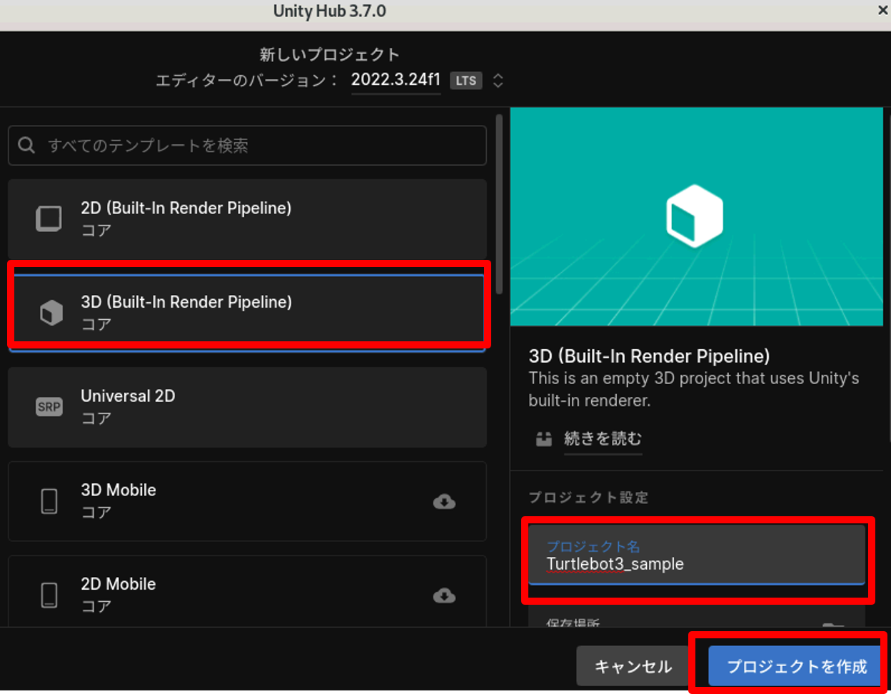
1. Unity Hubを起動し、右上の新しいプロジェクトを押します。

2. テンプレートは3Dを選択、プロジェクト名を設定後、「プロジェクトを作成」からUnityを開始します。
1. GitHubからTurtlebot3のURDFファイルをダウンロードします。
https://github.com/ROBOTIS-GIT/turtlebot3/tree/foxy-devel
2. ダウンロードしたファイルをUnityプロジェクトファイル内のAssetsディレクトリに格納します。
例: /ユーザ名/Turtlebot3_sample/Assets

3. UnityでURDFを取り込む仕様上、URDFのファイル構成を変更します
/turtlebot3/turtlebot3_description/urdf内に新しいディレクトリを作成し、turtlebot3_burger.urdfと、turtlebot3_description内のmeshesをそこにコピーします。
4. turtlebot3_burger.urdf内のstlのパスが書かれている部分の記述を下記に変更します。
変更前:<mesh filename=“package://turtlebot3_description/meshes/bases/burger_base.stl” scale=“0.001 0.001 0.001”/>
↓
変更後:<mesh filename=“package://meshes/bases/burger_base.stl” scale=“0.001 0.001 0.001”/>
※burger_base.stl、left_tire.stl、 right_tire.stl、lds.stlの4個所を変更する
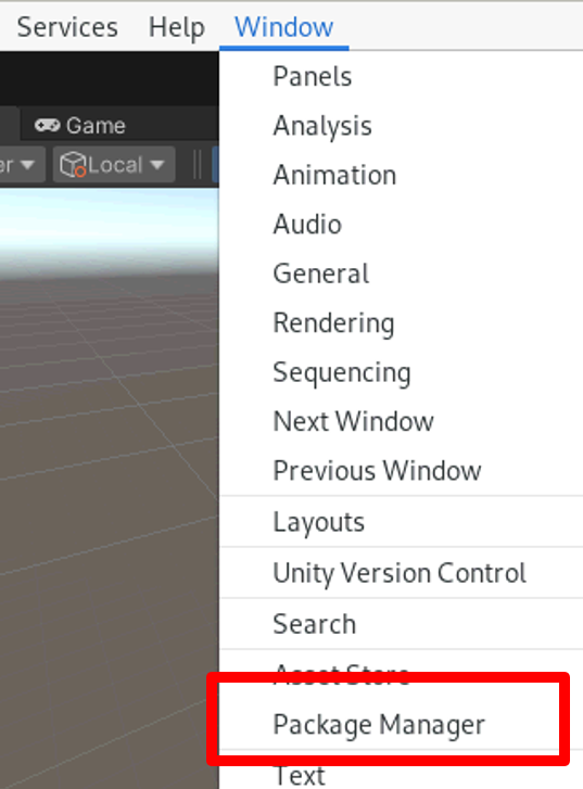
1. URDFを取り込むためのプラグインをダウンロードするため、Unity上部メニューのWindow->Package Managerを選択します。
2. Package Managerが開いたら、左上の+ボタンを押し、「Add package from git URL」を選択、ライブラリダウンロードのURL入力画面となるので
https://github.com/Unity-Technologies/URDF-Importer.git?path=/com.unity.robotics.urdf-importer#v0.5.2
を入力、Addを押し、Unity内にURDF Importerをインストールします。
1. Unity画面下部のProjectタブからAssets内にて用意したURDFがあるディレクトリに移動します。

2. URDF-Importerを起動するため、そのURDFファイルを右クリックし、「Import Robot from Selected URDF file」を選択します。
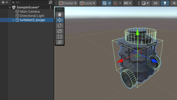
3. 表示されたウィンドウの「Import URDF」を押すことでTurtlebot3がUnity内に生成されます。
1. ROS2と通信するプラグイン「ROS-TCP-Connector」をダウンロードするため、Package Managerを開き、左上の+ボタンを押し、「Add package from git URL」を選択
2. ライブラリダウンロードのURL入力画面となるので
https://github.com/Unity-Technologies/ROS-TCP-Connector.git?path=/com.unity.robotics.ros-tcp-connector
を入力し、Addを押し、インストールを行います。
3. 上部メニューから新たに追加されたRobotics->ROS Settingsを選択します。

4. ROS2と通信するため、Protocol項目からROS1→ROS2に変更し、画面を閉じます。
1. ROS2から/odomを受信し、ロボットの位置に反映する下記のスクリプト(OdomSubscriber.cs)を作成します。
その後、Assetsディレクトリ内にScriptsディレクトリを作成、このスクリプトを格納します。
/odomを受信し、Unity内のロボットに反映させるスクリプト(OdomSubscriber.cs)
using UnityEngine;
using Unity.Robotics.ROSTCPConnector;
using Unity.Robotics.ROSTCPConnector.ROSGeometry;
using RosMessageTypes.Nav;

public class OdomSubscriber : MonoBehaviour
{
    public GameObject robot;
    private ROSConnection ros;
    private Vector3 initialPosition;
    private Quaternion initialOrientation;
    private bool initialPositionSet = false;

    void Start()
    {
        ros = ROSConnection.GetOrCreateInstance();
        ros.Subscribe("/odom", ReceiveROSMsg);
    }

    private void ReceiveROSMsg(OdometryMsg odomMsg)
    {
        //odomデータを格納
        //ROS-Unity間の座標系違いのためFromで変換
        //https://github.com/Unity-Technologies/ROS-TCP-Connector/blob/main/ROSGeometry.md
        Vector3 position = odomMsg.pose.pose.position.From();
        Quaternion orientation = odomMsg.pose.pose.orientation.From();

        //odomの初期値を保存
        if (!initialPositionSet)
        {
            initialPosition = position;
            initialOrientation = orientation;
            initialPositionSet = true;
        }

        // odomの初期値と現在値の差分を計算
        Vector3 robotPosition = position - initialPosition;
        Quaternion robotOrientation = orientation * Quaternion.Inverse(initialOrientation);

        // Unity内のロボットに反映
        robot.transform.GetComponent().TeleportRoot(robotPosition, robotOrientation);

    }
}
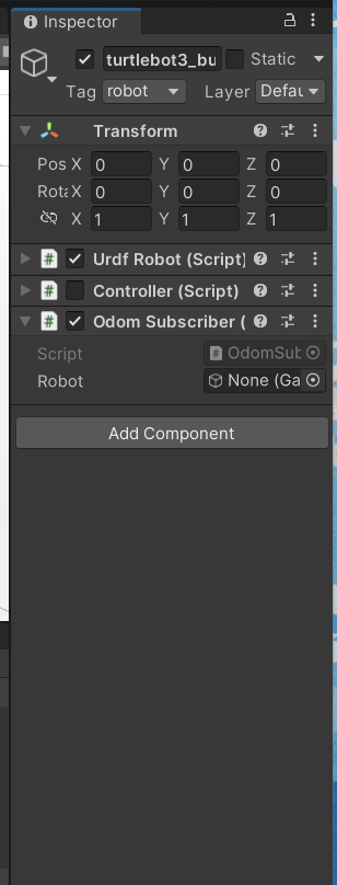
2. Unity左部のオブジェクト一覧からturtlebot3_burgerと書かれた項目を選択、このコードをProjectタブから選択、右側のプロパティ欄にドラッグ&ドロップを行います。
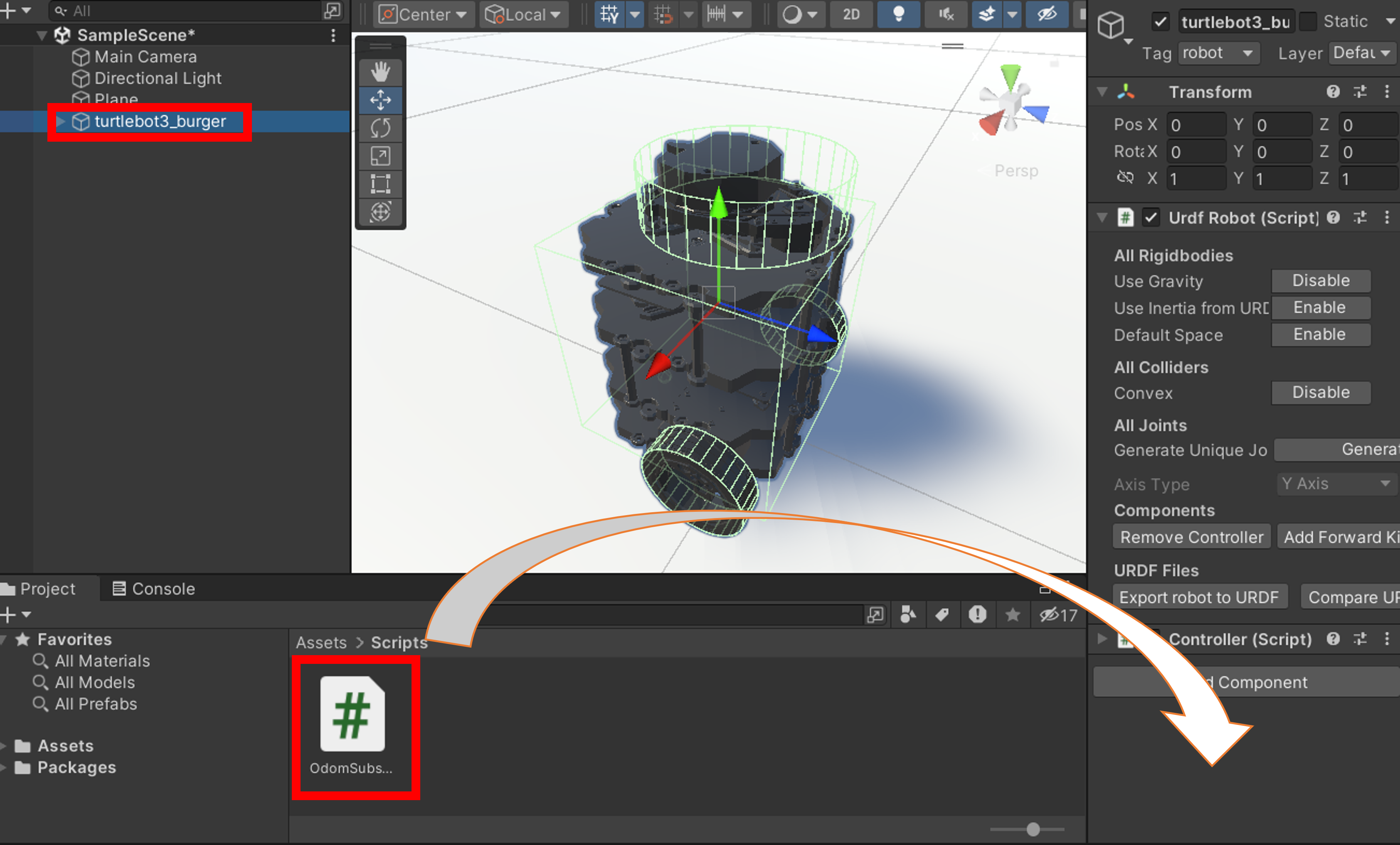
3. 右側プロパティ内のOdom Subscriber内のRobot欄からbase_linkを選択します。
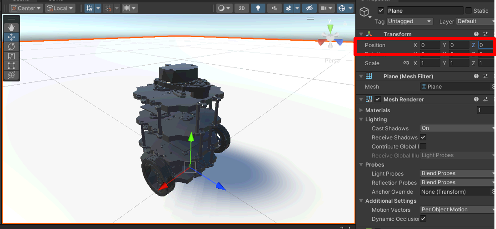
1. Unity左部のオブジェクト一覧を右クリックし、3D Object-> Planeを選択、床を生成します。
2. 右側のプロパティから床の座標を原点に調整し、タイヤの下に来るように調整します。
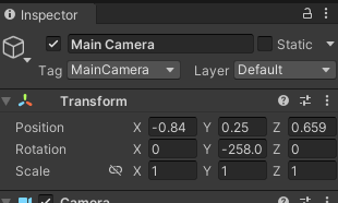
3. オブジェクト一覧からMain Cameraを選択し、シミュレーション再生時に見やすい画面にするために下記のような座標に設定します。
ここまでで、Unity側の準備は完了となります。
1. 下記URL参考にTurtlebot3のライブラリのインストールを行います。
参考:https://emanual.robotis.com/docs/en/platform/turtlebot3/quick-start/#pc-setupのFoxyタブの項目3.1.3、3.1.4
2. Unity側とROS通信をするためのライブラリ「ROS-TCP-Endpoint」、そしてTurtlebot3のGazebo環境をダウンロード、ビルドを行います。
$ cd ~/colcon_ws/src
$ git clone -b foxy-devel https://github.com/ROBOTIS-GIT/turtlebot3_simulations.git
$ git clone -b main-ros2 https://github.com/Unity-Technologies/ROS-TCP-Endpoint
$ cd ~/colcon_ws
$ colcon build
1. Unity側の再生ボタンを押し、Unityのシミュレーションを開始します。
2. 新しいターミナルを起動し、そこからTurtlebot3のGazeboシミュレーションを起動します。
$ source ~/colcon_ws/install/setup.bash
$ export TURTLEBOT3_MODEL=burger
$ ros2 launch turtlebot3_gazebo turtlebot3_world.launch.py
3. さらに新規ターミナルを起動、ROS2側でROS-TCP-Endpointを実行し、Unityとの通信を可能にする状態にします。
$ source ~/colcon_ws/install/setup.bash
$ ros2 run ros_tcp_endpoint default_server_endpoint
4. 3つ目の新規ターミナルを開き、Turtlebot3の操作プログラムを実行します。
$ source /opt/ros/foxy/setup.bash
$ export TURTLEBOT3_MODEL=burger
$ ros2 run teleop_twist_keyboard teleop_twist_keyboard
ここまでで、GazeboとUnityの位置同期を行いました。ここではUnity側のロボットにセンサーを設定し、障害物との距離でGazebo側のロボットも自動停止させることを実行します。
1. UnityにてROSにセンサーを設置し、情報をROSに送信するため下記のスクリプトを使用するため、URLからROS対応センサーのスクリプトをダウンロードします。
https://github.com/Unity-Technologies/Robotics-Nav2-SLAM-Example/blob/main/Nav2SLAMExampleProject/Assets/Scripts/LaserScanSensor.cs
2. プロジェクト内のScriptsディレクトリにダウンロードしたコードを格納します。
3. Unity左部のオブジェクト一覧からbase_scanを選択し、格納したコードを右側のプロパティにドラッグ&ドロップを行います。
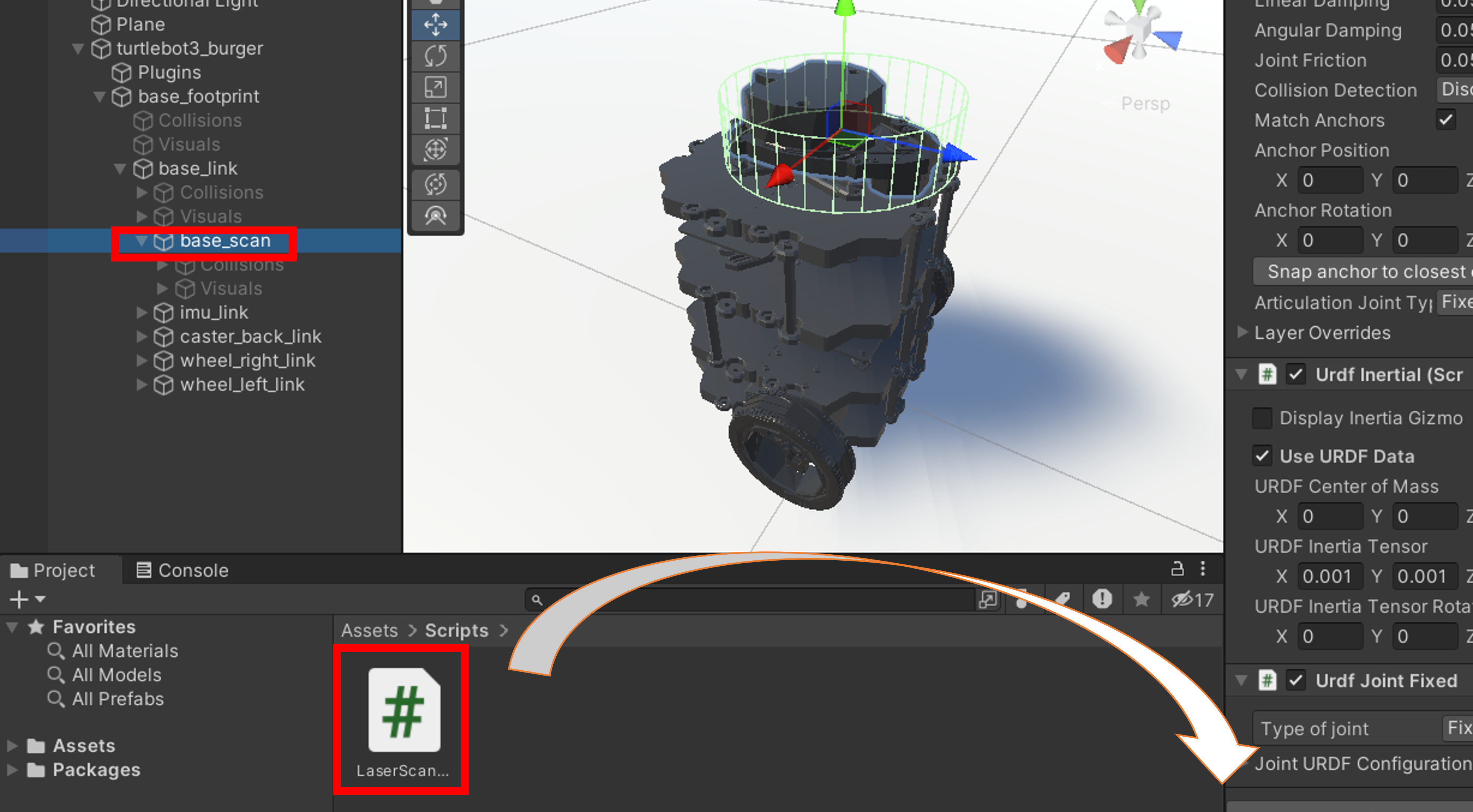
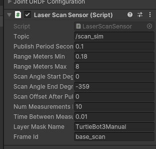
4. 追加されたLaserScanSensorのプロパティ値は下記のように設定します。
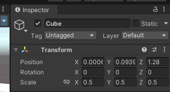
1. Unity左側を右クリックし、3D Object-> Cubeを選択し、障害物となる立方体を設置します。
座標、サイズは下記のように設定を行います。
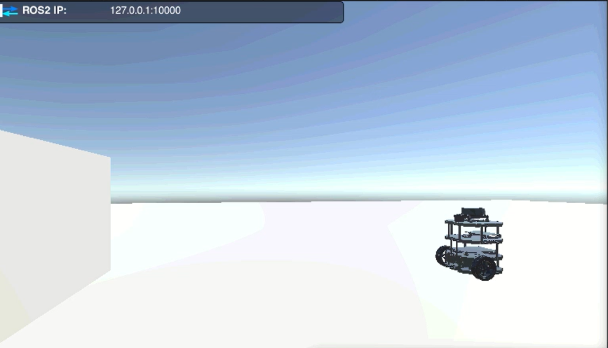
2. シミュレータを開始すると、下記のような形となります。
1. Pythonで下記のコード(ObstacleStopper.py)を作成し、任意の場所に保存を行います。
# -*- coding: utf-8 -*-
#!/usr/bin/env python3
import rclpy
from rclpy.node import Node
from sensor_msgs.msg import LaserScan
from geometry_msgs.msg import Twist
from rclpy.qos import QoSProfile, QoSReliabilityPolicy, QoSDurabilityPolicy

class ObstacleDetector(Node):
	def __init__(self):
		super().__init__("obstacle_detector")

		self.cmd_vel_pub = self.create_publisher(Twist, "cmd_vel", 10)
		self.cmd_vel2_sub = self.create_subscription(Twist, "cmd_vel2", self.cmd_vel2_callback, 10)
		self.scan_sim_sub = self.create_subscription(LaserScan, "scan_sim", self.scan_sim_callback, 10)
		self.obstacle_sim_flg = False

	def cmd_vel2_callback(self, msg):
		#センサーと障害物が閾値(今回は35cm)以下の場合は速度0、そうでなければ受信した値をそのまま送信
		if self.obstacle_sim_flg:
			msg.linear.x = 0.0
			msg.angular.z = 0.0
		self.cmd_vel_pub.publish(msg)

	#受信したセンサーの最短値が閾値以下かを判定
	def scan_sim_callback(self, scan):
		range_ahead = scan.ranges[0]
		print("sim:", range_ahead)
		self.obstacle_sim_flg = self.detect_obstacle(range_ahead)

	def detect_obstacle(self, range_ahead):
		return range_ahead < 0.35

def main(args=None):
	rclpy.init(args=args)
	obstacle_detector = ObstacleDetector()
	rclpy.spin(obstacle_detector)
	obstacle_detector.destroy_node()
	rclpy.shutdown()

if __name__ == "__main__":
	main()
1. Unity側の再生ボタンを押し、Unityのシミュレーションを開始します。
2. 新しいターミナルを起動し、そこからTurtlebot3のGazeboシミュレーションを起動します。
$ source ~/colcon_ws/install/setup.bash
$ export TURTLEBOT3_MODEL=burger
$ ros2 launch turtlebot3_gazebo turtlebot3_world.launch.py
3. さらに別のターミナルを起動、ROS2側でROS-TCP-Endpointを実行し、Unityとの通信を可能にする状態にします。
$ source ~/colcon_ws/install/setup.bash
$ ros2 run ros_tcp_endpoint default_server_endpoint
4. 3つ目の新しいターミナルを起動し、上記で作成したPythonプログラムの実行を行います。
$ source /opt/ros/foxy/setup.bash
$ python3 ObstacleStopper.py
5. 別のターミナルから/cmd_vel2のトピックを送信します。
$ source /opt/ros/foxy/setup.bash
$ ros2 topic pub /cmd_vel2 geometry_msgs/Twist '{linear:  {x: 0.02, y: 0.0, z: 0.0}, angular: {x: 0.0,y: 0.0,z: 0.0}}' --hz 10
6. すると、下記の動画のようにUnity側のロボットと障害物の距離が一定距離以下(今回は35cmとなった場合、両シミュレータのロボットが止まることが確認することができます。
※シミュレーション上ではLiDARセンサーの様子は確認できませんが、動画のようにRviz2から確認することが可能です。
7. 新しいターミナルを起動後、ROS2側でROS-TCP-Endpointを実行し、Unityとの通信を可能にする状態にします。
$ source ~/colcon_ws/install/setup.bash
$ ros2 run ros_tcp_endpoint default_server_endpoint
8. 別のターミナルからRviz2を起動します。
$ source ~/colcon_ws/install/setup.bash
$ rviz2
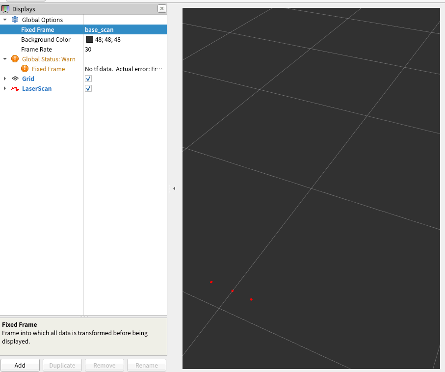
9. Rviz2上で下のAddを選択、表示された画面からBy Topic一覧タブから/scan_simのLaseScanを選択し、OKを押します。
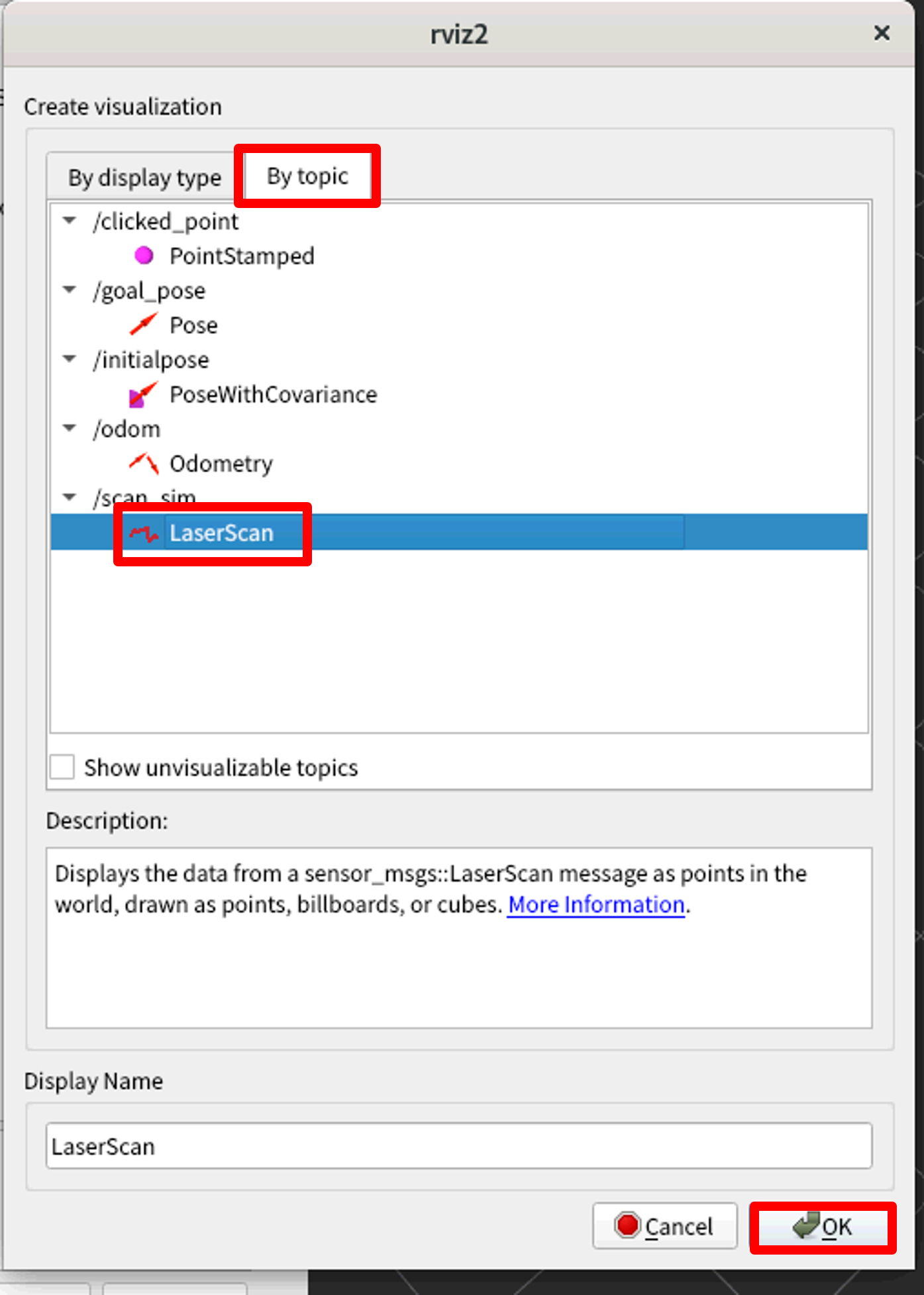
10. 左プロパティのFixed Frameのプロパティ欄にbase_scanと入力すると右画面にてロボットと障害物の間を表す赤い点が確認できます。
本記事では、Turtlebot3の位置同期とセンサーによる制御をUnityとGazeboを使用して実装しました。以前、Isaac Simでも同様の実装を行いましたが、Isaac SimにはセンサーやROS対応など、ロボットシミュレータとして必要な機能がすでに内蔵されており、一方でUnityでは別途ライブラリの用意やコーディングが必要でした。ただし、Unityは使用人口が多いため、参考資料や第三者によるライブラリも多く利用できるため、どちらのシミュレータを扱うかは一長一短であると思われます。いずれのシミュレータも当社で取り扱い可能ですので、お気軽にご相談ください。
ロボットシミュレータにお困りの方はぜひ、
富士ソフトにご用命ください!